


The prime function of a Rotary Valve is to regulate the flow of dust, powder and granular products from one chamber to another whilst maintaining a good airlock.
In the dust filtration field a good airlock is essential on cyclone and bag filter applications in order that the manufacturers quoted high dust collection efficiencies can be maintained. Airlocks are also important in the pneumatic conveying industry, where product is regulated into a pressure or vacuum conveying line while minimising air leakage.
With Rotolok there are no double standards, all our standard valves are precision machined for close tolerances and minimal eccentricities.
Pressure differentials to 20psi and temperatures to 400°C (752°F) are considered the norm and extreme pressures and temperatures can be accommodated with special designs. If your application requires such considerations contact the Rotolok Engineering team.
Rotolok Rotary Valves and Airlocks have ATEX Covered
Following successful completion of the rigorous testing process Rotolok can offer a complete range of Rotary Valves certified as suitable for use as an explosion barrier to a maximum of 10bar and for explosion isolation for St1 and St2 dusts.
Due to careful design of the internal components the overall dimensions are very similar to our standard range of valves and we can offer a selection of optional features such as purged shaft seals, scalloped rotor pockets and staggered rotor pockets without the throughput being greatly reduced or the barrier efficiency being affected.

-
Bodies
Cast Iron, Stainless Steel or Aluminium precision bored.
-
End Covers
Cast Iron, Stainless Steel or Aluminium spigot located inbody for concentricity.
-
Rotor
Fabricated Mild or Stainless Steel.
-
Bearings
Sealed-for-life ball type rigged outboard.
-
Shaft Seal
Gland type with PTFE packing.
-
Drive
TEFC geared motor unit side wall mounted to valve body and complete with taper lock sprockets and chain drive all in an enclosed guard.
- Quick Release Rotors
- Direct Coupled Drives
- Air Purge Glands
- Body Vents
- Vent Boxes
- Dropout Boxes
- V.S. Drives
- Speed Switches
- Flameproof Motors
- Shear Plate Deflectors
- Electroless NickelPlating
- Hard Chrome Internals etc.

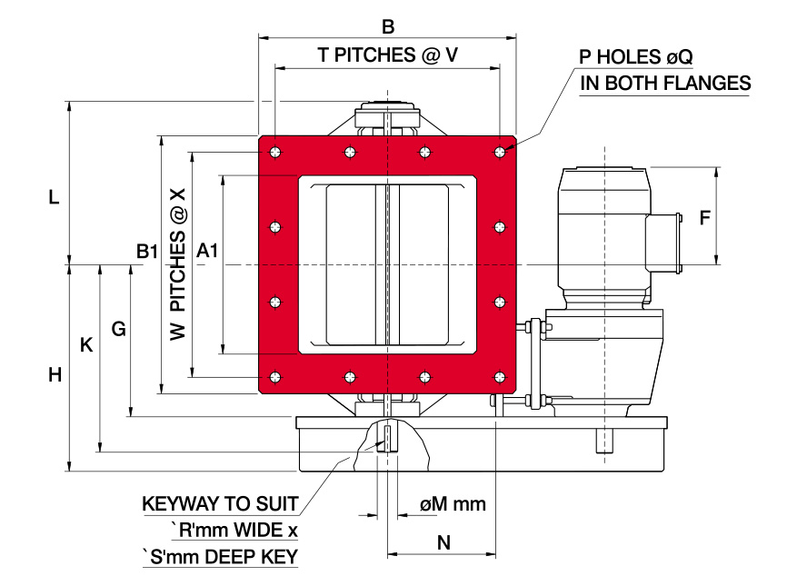
All dimensions are in mm unless otherwise stated
| Size | A | A1 | B | B1 | C | D | E | F | G | H | J | K | L | M | N | P | Q | R | S | T | V | W | X | kW |
|---|---|---|---|---|---|---|---|---|---|---|---|---|---|---|---|---|---|---|---|---|---|---|---|---|
| 125 | 127 | 127 | 225 | 225 | 12 | 98.5 | 197 | 195 | 159 | 232 | 406 | 220 | 195 | 28 | 143 | 8 | 14 | 8 | 7 | On Application | 0.37 | |||
| 150 | 152 | 152 | 152 | 250 | 12 | 140 | 280 | 180 | 174 | 247 | 406 | 234 | 195 | 28 | 143 | 12 | 12 | 8 | 7 | 3 | 70 | 3 | 70 | 0.37 |
| 200 | 203 | 203 | 300 | 300 | 15 | 165 | 330 | 155 | 199 | 272 | 406 | 259 | 219 | 18 | 143 | 12 | 12 | 8 | 7 | 3 | 90 | 3 | 90 | 0.37 |
| 250 | 254 | 254 | 370 | 370 | 15 | 203 | 388 | 200 | 229 | 322 | 478 | 290 | 249 | 35 | 155 | 12 | 18 | 10 | 8 | 3 | 108 | 3 | 128 | 0.75 |
| 300 | 305 | 305 | 440 | 440 | 19 | 240 | 465 | 170 | 260 | 353 | 478 | 320 | 279 | 35 | 195 | 12 | 18 | 10 | 8 | 3 | 128 | 3 | 128 | 0.75 |
| 350 | 356 | 356 | 470 | 470 | 19 | 257 | 514 | 160 | 270 | 363 | 512 | 329 | 289 | 35 | 220 | 12 | 12 | 10 | 8 | 3 | 140 | 3 | 140 | 0.75 |
| 400 | 406 | 406 | 550 | 550 | 20 | 300 | 580 | 115 | 332 | 425 | 626 | 403 | 352 | 50 | 235 | 12 | 18 | 14 | 9 | 3 | 165 | 3 | 165 | 1.1 |
| 450 | 457 | 457 | 610 | 610 | 20 | 322 | 630 | 85 | 357 | 450 | 626 | 428 | 377 | 50 | 285 | 12 | 18 | 14 | 9 | 3 | 187 | 3 | 187 | 1.1 |
| 500 | 508 | 508 | 650 | 650 | 20 | 340 | 670 | 120 | 382 | 475 | 700 | 453 | 402 | 50 | 289 | 16 | 18 | 14 | 9 | 4 | 148 | 4 | 148 | 1.5 |
| 600 | 610 | 610 | 750 | 750 | 20 | 380 | 750 | 115 | 432 | 525 | 700 | 503 | 452 | 50 | 335 | 16 | 18 | 14 | 9 | 4 | 173 | 4 | 173 | 2.2 |
| 750 | 750 | 750 | 1000 | 1000 | 25 | 500 | 1000 | 60 | 503 | 643 | 910 | 605 | 522 | 70 | 450 | 24 | 18 | 20 | 12 | 6 | 149 | 6 | 149 | 2.2 |
| 915 | 915 | 915 | 1165 | 1165 | 25 | 600 | 1200 | -25 | 605 | 748 | 1000 | 707 | 625 | 70 | 540 | 24 | 22 | 20 | 12 | 6 | 175 | 6 | 175 | 4.0 |


All dimensions are in mm unless otherwise stated
| Size | A | B | C | D | E | F | G | H | J | K | L | M | N | O | P | Q | R | S | kW |
|---|---|---|---|---|---|---|---|---|---|---|---|---|---|---|---|---|---|---|---|
| 50 | 51 | 152 | 10 | 60 | 120 | * | 74 | On Application | |||||||||||
| 85 | 85 | 190 | 10 | 80 | 80 | * | 117 | On Application | |||||||||||
| 125 | 127 | 240 | 12 | 108 | 108 | 200 | 159 | 232 | 406 | 219 | 178 | 28 | 143 | 8 | 18 | 200 | 8 | 7 | 0.37 |
| 150 | 154 | 285 | 12 | 140 | 270 | 180 | 174 | 247 | 406 | 234 | 194 | 28 | 143 | 8 | 22 | 241 | 8 | 7 | 0.37 |
| 200 | 203 | 320 | 13 | 160 | 310 | 155 | 199 | 272 | 406 | 259 | 219 | 28 | 143 | 8 | 18 | 280 | 8 | 7 | 0.37 |
| 250 | 254 | 370 | 15 | 200 | 380 | 200 | 229 | 322 | 478 | 289 | 248 | 35 | 155 | 8 | 18 | 320 | 10 | 8 | 0.75 |
| 300 | 305 | 440 | 19 | 240 | 465 | 170 | 260 | 353 | 478 | 320 | 279 | 35 | 195 | 12 | 22 | 395 | 10 | 8 | 0.75 |
| 350 | 356 | 533 | 19 | 270 | 520 | 160 | 270 | 363 | 512 | 332 | 289 | 35 | 220 | 12 | 22 | 445 | 10 | 8 | 0.75 |
| 400 | 406 | 540 | 20 | 300 | 580 | 110 | 332 | 425 | 626 | 403 | 352 | 50 | 235 | 12 | 22 | 495 | 14 | 9 | 1.1 |
| 450 | 457 | 635 | 20 | 320 | 625 | 80 | 357 | 450 | 626 | 419 | 377 | 50 | 285 | 16 | 32 | 578 | 14 | 9 | 1.1 |
| 500 | 508 | 700 | 20 | 340 | 670 | 115 | 382 | 475 | 700 | 453 | 402 | 50 | 289 | 20 | 32 | 635 | 14 | 9 | 1.5 |
| 600 | 610 | 813 | 20 | 385 | 760 | 115 | 432 | 525 | 700 | 503 | 452 | 50 | 335 | 20 | 35 | 749 | 14 | 9 | 2.2 |
| 750 | 762 | 984 | 25 | 500 | 1000 | 45 | 503 | 646 | 910 | 605 | 522 | 70 | 450 | 28 | 35 | 914 | 20 | 12 | 2.2 |
Restricted Content
This page contains content that is available to registered users only.
To view the restricted content, please log in or create an account to gain access to view the resources.
Login
Register for account
Register* Once your account has been approved , your password will be autogenerated and emailed to your registered e-mail address